intermittant added text:
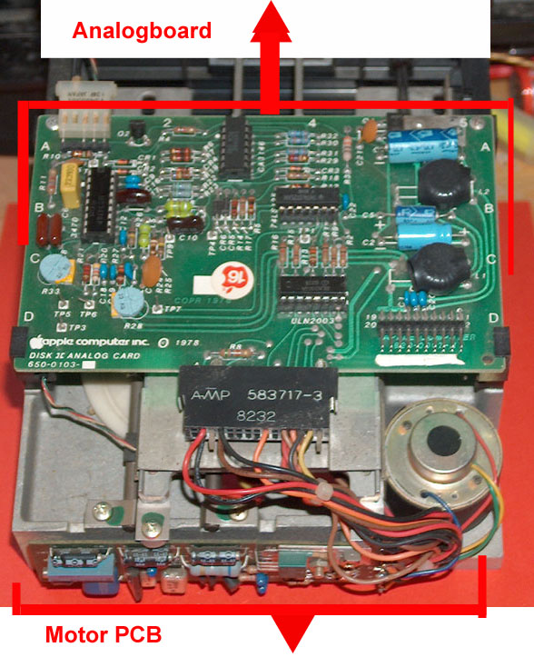
1. the cable from "Analog
board" to read/write head is not shielded and it transmits
delicate signal...
possible solution:
changing that very thin cable to a very thin shielded special
microphon-cable
( with isolated 4 "core" wires !)
the problem: this special shielded very thin cables are very
rare (!) and very extreme expensive (!)
hard to get (!) and you have to find one, that
is exactly same flexible
like the unshielded one formely used and to be replaced
and you have to be very
careful while soldering ( the read/write head is very
sensible ! )short research:
http://ex-en.alliedelec.com/search/productdetail.aspx?SKU=70004649#tab=specs
or
http://www.gotham.ch/en/index.php?section=docsys&cmd=23_details&id=15
-It is even not sure that this cables
will fit the needs....
- first cable seems not to be flexible enough
and second seems to fit ... - if it is thin enough
- it must be previously issued some questions to the seller:
is the "total"-cable ( refering to the outer diameter of the
cable )
really very thin ( less 3mm ) and very extreme flexible ?
- and
shielding of that cable
must be connected to
Ground of the analog board
- but none of the four "core"-cables in
that cable is connected to ground
- therfor there must be
a fifth connection made to the shielding of that cable
isolated from the other four cables
- and the connection to Ground must be
made
at the analog board side
- at the read/write head the shielding
must remain without connection
staying isolated
from the four "core" wires ! - and being covered
with shrinkhose for pretection against unwanted contacts !.
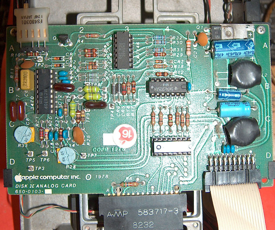
2. as explained the signals to the
read/write head are very sensible - so at most drives the
read/write compensation signal is just adjusted in a "standard
general" way ....
- as far as you tell not to be technician
i would give advice to
only let experienced tecnician
perforn the task:
adjusting the read/write compansation at the analog board with
control at a oscilloscope
as explained in my disk pages - this optimizese the signals
from and to the read/write heads cleaing them from unwanted
spikes and "dirt impulses"....
3. often forgotten: if disk drive is
dismounted often the shielding plate is removed to attempt the
parts below...
and often its not realy mounted back properly....
it's also good idea to get better
electrical connection of the shielding plate to "solid
electrical ground" -
it's funny that
engineers at Apple didn't be aware of the leaking connection
between shielding plate and ground... the diskframe is
only bad electrical connection:
solution: solder a
flexible wire to the shielding plate and at the other end of the
( rather short ! ) flexible wire mount a pin- connector and add
( +close to the large filtering capacitors at the analog bord at
their minus pol ( which is the general ground of the drive ) a
pin where that wire connector may be attached to....
this ensures nmuch better operation of the shielding function of
the shielding plate....
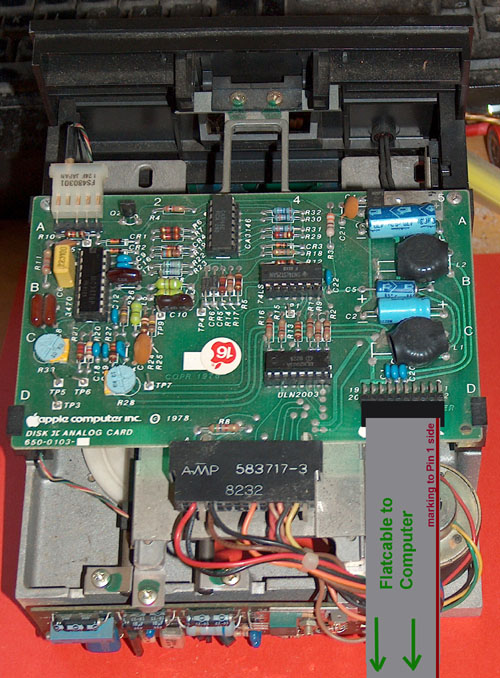
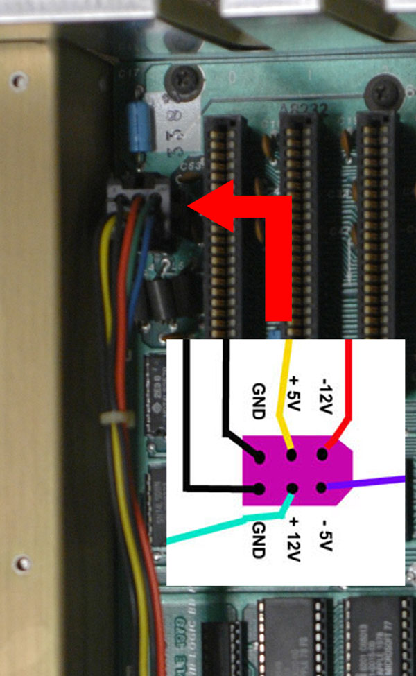
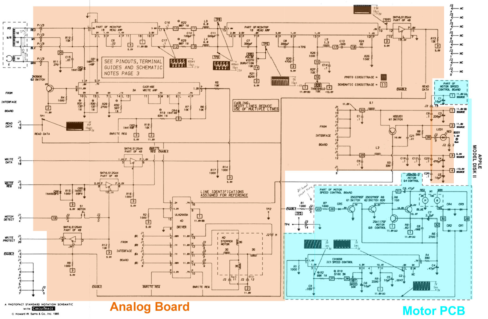
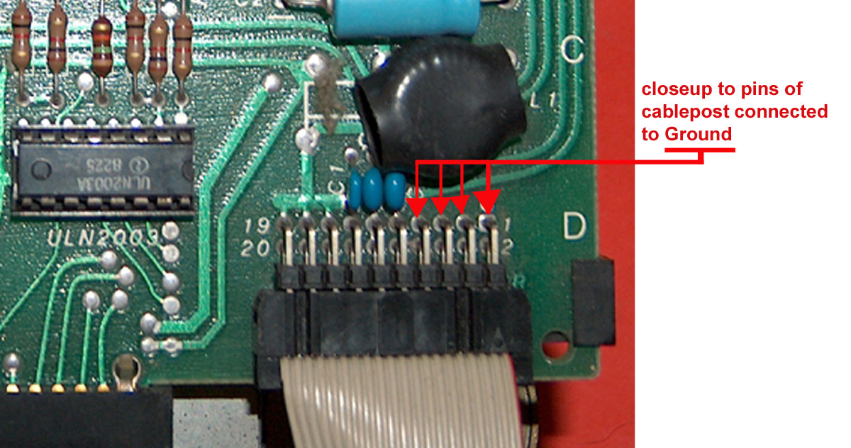
Hint to
find Ground at the analog board: Pin 1,3,5 and 7 at
the connector of the analog board to the plug of the cable to
the interface are connected to Ground
and just
besides also another hint: some guys equipped in
former days their drives with longer flatribbon cables
that's not a good idea....
this cable should be really not longer than 2 feet ( = 60 cm
)......
and even the guys at Apple recognized the problem of unshielded
flatribbon cable to the drives ....
at least if using the drive roughly and often its better to
replace the old unshielded "rainbow" cables with the later used
gray flatribbon cables with the attached "mounting plates" -
they are shielded and perform their duty much better than the
old "rainbow" like cables....
( see pictures of both cables displayed below ! )
also to be mentioned here....
often in former days users have forgotten while dismounting
cable from disk drive to interface from the drive
to remount
back the inductive core !
That's the cluby ferron ring where the cable has been wrinkled
several times through before being attached to the analog
board....
that inductive core shall be mounted and
the cable should make 3
turns through that core and be mounted between the analog
board and the fixing clamp at the rearside of the case !
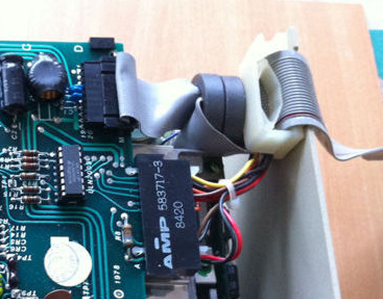 |
<= This left picture
shows the better
grey partially shielded cable monted
correct with 2 turns in
the inductive
core.
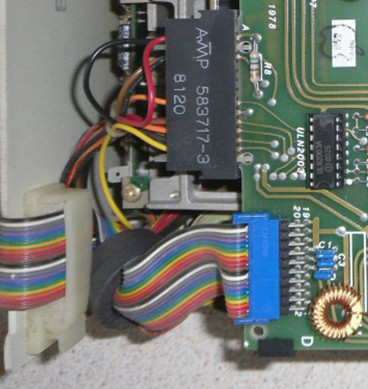
this
right picture displays the older =>
not so good "rainbow" cable and
it also displays mistake:
the cable
runs straight through the inductive
core without windings !
|
 |
all this
points will lead to better and more reliable performance of the
DISK II drives. |